Lightning Protection Zoning in Steel Offshore Substations: Practical Engineering Challenges
Lightning protection offshore substation in steel structures requires proper LPZ zoning to prevent surge damage to LV/ICT. Renova Energy Solutions explores bonding, SPD placement and entry risks – plus early zoning strategies to avoid costly rework.
RISK IDENTIFICATION & MITIGATION
George Ralston
1/5/20264 min read
Steel offshore substations provide inherent shielding due to their conductive structure, yet this benefit is frequently overstated. Without properly defined Lightning Protection Zones (LPZ), surge voltages, induced currents, and electromagnetic disturbances can propagate into sensitive LV and ICT systems.
In offshore wind projects, LPZ misapplication or omission has repeatedly resulted in unexpected surge damage, EMC non-conformities, or intermittent faults during lightning testing or early operations. These issues rarely arise from poor surge protection devices (SPD) alone; they stem from undefined zoning, inconsistent bonding, and uncoordinated cable entry strategies.
When LPZ concepts are deferred or treated as secondary to primary lightning protection, problems emerge late — during FAT surge testing, commissioning, or post-energisation events — when retrofits become logistically complex and costly.
The Technical Nature of the Problem
Lightning protection for offshore steel structures follows principles in IEC 62305 (Protection against lightning), adapted for marine environments. Key elements include:
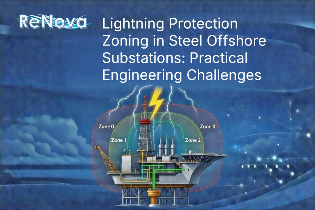
LPZ 0 — External zone (exposed to direct strikes and full lightning electromagnetic pulse)
LPZ 1 — Internal zone (shielded by structure, reduced fields)
LPZ 2+ — Further shielded areas (e.g., inside cabinets or Faraday-like enclosures)
In steel substations, the platform acts as a partial Faraday cage, but cable entries, penetrations, and unbonded interfaces create vulnerabilities. Surge currents can couple into LV feeders, fibre optics, instrumentation, or control circuits via:
Common-mode currents on cable shields
Ground potential rise differences
Magnetic field induction through large loops
Inadequate equipotential bonding at entries
Common challenges include:
Undefined LPZ boundaries within the topsides
Inconsistent SPD placement and coordination (Type 1/2/3)
Poor shield termination at zone transitions
Unbonded metallic penetrations allowing field penetration
Mismatched grounding philosophies between HV, LV, and ICT systems
These gaps allow surges to bypass external protection and affect internal electronics, leading to component stress or data corruption.
Where It Breaks Down in Practice
LPZ definition often occurs late or inconsistently across disciplines.
During FEED, lightning risk assessments may focus on external air terminals and down-conductors, deferring internal zoning.
In detailed design:
Structural teams define external LPS
Electrical teams specify SPDs
Instrumentation/telecomms teams handle shield bonding
Cable routing proceeds without zone-aware philosophy
Each discipline complies locally, but integration reveals gaps.
Repeatedly observed issues include:
Cable entries without zone-specific bonding (e.g., shields grounded only at one end)
SPDs placed without clear LPZ transition coordination
Metallic penetrations or trays not bonded to structure at zone boundaries
Grounding inconsistencies between power and signal systems
A typical example from recent North Sea offshore substation projects involved a steel topsides where fibre-optic and instrumentation cables entered through unbonded bulkhead penetrations. The external LPS was well-designed, but no formal LPZ 0/1 boundary was defined at entries. Shields were terminated only at equipment end per vendor spec.
During onshore surge immunity testing (simulated lightning-induced transients), induced voltages appeared on signal lines, causing intermittent relay malfunctions and data errors. Root cause traced to magnetic coupling through the penetration loop. Rework required additional bonding straps, surge filters, and shield re-termination at the entry — delaying module completion by 10–14 days and adding engineering and material costs.
The issue originated from deferred LPZ concept development before cable routing freeze; an earlier cross-discipline zoning review would have enforced bonding at the zone interface at minimal cost.
The Commercial and Programme Consequence
LPZ rework rarely manifests as dramatic strike damage — offshore lightning events are infrequent during build. Yet it accumulates exposure through:
Onshore surge re-testing and retrofits
Additional bonding hardware and labour
Vendor variation claims for scope changes
Extended FAT or re-verification cycles
Potential operational constraints (e.g., restricted use of sensitive systems in storm-prone seasons)
If discovered offshore, interventions involve confined-space access, partial de-energisation, and weather-dependent windows — escalating costs significantly.
Unresolved surge paths can lead to intermittent faults that are difficult to diagnose, eroding confidence in system reliability.
The impact is programme delay, increased variation, and reduced operational robustness.
A Structured Prevention Approach
Effective LPZ implementation requires treating zoning as an integrated design philosophy from early stages.
Practical measures that consistently reduce risk:
Define LPZ Concept at Concept/FEED Stage Establish boundaries aligned with structure, cable entries, and equipment locations. Document zone transitions and bonding requirements.
Coordinate Bonding at Zone Interfaces Mandate equipotential bonding of all metallic penetrations, trays, and shields at LPZ boundaries. Require single-point or multi-point grounding per zone rules.
Specify and Coordinate SPDs Place coordinated SPDs (Type 1 at entries, Type 2 internally) with clear zoning rationale. Verify energy coordination across types.
Integrate Zoning into Routing Reviews Conduct cross-discipline reviews of cable entries and routing before layout freeze. Verify shield termination and loop minimisation against LPZ.
Document and Verify Maintain a traceable LPZ matrix (entry ID → zone transition → bonding method → SPD placement). Audit during model reviews and FAT.
These steps emphasise early coordination over additional hardware — shifting risk to design phases.
Engineering-Led Risk Reduction
In steel offshore substations, the structure offers shielding potential — but only when LPZ is deliberately engineered.
Across projects, zoning issues rarely stem from neglecting lightning protection entirely. They result from deferred internal zoning, inconsistent bonding, and interface fragmentation.
Early, structured LPZ definition — supported by bonding coordination and entry reviews — eliminates most surge propagation surprises. It protects LV/ICT integrity, ensures EMC compliance, and safeguards commissioning schedules.
Offshore platforms operate in harsh electromagnetic environments. Treating lightning zoning as integrated engineering rather than an add-on is a proportionate response to the asset's value and exposure.
This article is part of Renova's Offshore Substation Auxiliary Systems Risk Series, comprising:
Contact
Prefer to call us directly, or send an email?
Phone
+39 331 802 9277 (Europe)
+1 281 932 6226 (USA)
© 2022 Renova Energy Solutions LLC. Registered in WY, USA. Operating from USA/Italy
All rights reserved.
Projects delivered in conformity with ISO 9001 quality management principles, DNV, and Lloyd's Register standards in renewable energy and marine sectors. [Learn more about us →]